 |
|
Engines
|
|
|
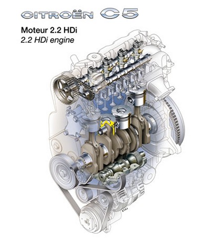
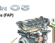
2.2 HDi
engine (DW12ATED) and particle
filter (PF)
-
The highly
reputed HDi engines offer the following major
advantages :
-
lower fuel
consumption ;
-
increased
driving comfort (greatly reduced noise and
vibration, plus high torque at low engine speeds)
;
-
low exhaust
emission levels.
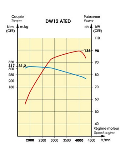
The
2,179 cm3 2.2 HDi unit develops a maximum power output
of 98 kW (136
bhp) at 4,000 rpm, with torque of 317 Nm (31.2 m.kg)
at 2,000 rpm.
The
engine uses common-rail direct injection technology
(high pressure,
1,350 bars), with combustion chamber geometry designed
for maximum fuel
/ air mixing. Engine design has been optimised to
reduce friction and
component weight, especially for moving parts.
State-of-the-art
technologies used on the engine include the
variable-geometry
turbocharger, an air inlet system with a butterfly
choke valve
providing variable swirl, two balancer shafts to
reduce vibration, and
a twin-damped engine flywheel.
Camshafts and
valves
The
aluminium cylinder head is fitted with two cast
camshafts linked by a
drive chain. The camshafts act on 16 valves by means
of roller cam
followers and hydraulic tappets that take up any play
in the system.
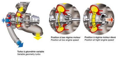
Variable
geometry turbocharger
The
variable geometry turbocharger provides increased
turbocharge pressure
at low engine speeds and improved maximum power output
at high engine
speeds.
At low
engine speeds, the cross-sectional area of the exhaust
gas nozzles
driving the turbine is reduced to increase the
pressure of the gas
hitting the turbine blades with a consequent increase
in turbocharge
pressure. In contrast, at high engine speeds, the gas
nozzles open
progressively under the control of the engine control
unit to reduce
the turbocharge pressure.
The
engine control unit controls a piston that varies the
gas nozzle
diameter by means of a pneumatic capsule in response
to driver demand
(engine speed and load) and data from the pressure
sensor located
downstream of the air-to-air intercooler.
|
|
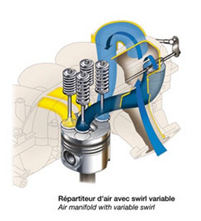 |
Variable
swirl air inlet
The
variable swirl system increases the rotational
movement of the air in
the combustion chamber to ensure that the fuel is
completely burned.
This ensures high performance and low emissions.
The
air intake system includes a helical air duct, causing
the air flow to
rotate into a vortex (swirl), and a tangential duct
providing an axial
flow. The tangential duct is fitted with a butterfly
valve that opens
when the engine reaches a preset speed (2,100 rpm at
80 °C) and the
injection rate reaches a preset flowrate (40 mg per
cycle).The
formation of particles at low engine speeds is reduced
as a result of
the improved fuel / air mixing in the swirl. At higher
engine speeds,
more air flows through the tangential duct and the
swirl is reduced,
thereby optimising airflow into the combustion
chamber.The piston tops
are machined to provide valve clearances, a central
dome and the cavity
needed to create the swirl.
The injectors,
located centrally in the combustion chamber, ensure
uniform fuel spray.
|
|
Twin-damped
engine flywheel
This
flywheel damps out cyclical variations at low engine
speeds. These
variations in crankshaft acceleration give rise to
vibration in the
vehicle drive train, especially gearbox rattle.
They
are a major source of noise at low engine speeds, from
1,200 to 2,400
rpm. The twin-damped flywheel filters out these
cyclical variations by
increasing gearbox inertia and reducing the stiffness
of the damping
hub.
|
|
The end result
is improvement in driving comfort and reduction in
noise and vibration.
Balancer
shafts
Two balancer
shafts reduce rotating assembly vibration.
The
masses on the shafts are at their lowest position when
a pair of
pistons are at top dead centre. The two shafts are
driven by the
crankshaft and mounted on a unit within the sump.
|
 |
|
Emission
control
Exhaust
gases are recycled to minimise release of NOx
(nitrogen oxides). The
emission control subsystem consists of three main
components :
-
an
exhaust gas recirculation (EGR) valve
(proportional solenoid valve
controlled by the engine control system)
recirculates some of the
exhaust gases back to the engine
-
air inlet ;
-
an
air / water intercooler located immediately after
the EGR valve cools
the recycled gas to increase its density and
thereby maximises mass per
unit volume for engine infeed ;
-
a
butterfly valve located in the air inlet is
controlled by the engine
control unit to adjust airflow according to engine
speed, load and
temperature.
Because of the
high injection pressure, no pre-heating is required if
the engine is started at ambient temperatures above 0
°C.
The oil-change
service interval is 20,000 km if a semi-synthetic oil
such as Total 10W40 is used.
|
|
|
|
Particle
filter (PF)
Particles
have a diameter of around 0.09 microns and consist
mainly of carbon and
hydrocarbons. The PF traps these particles and
periodically burns them
off.
Particles
burn naturally at approximately 550 °C, but the normal
temperature of
exhaust gases leaving the manifold is only 150 °C.
The particle
filter system overcomes this problem in a number of
ways :
-
post-injection
during
the expansion phase, resulting in post-combustion
in the
cylinder and a 200 to 250 °C increase in exhaust
gas temperature (i.e.
to between 350 and 400 °C) ;
-
additional
post-combustion by means of an oxidising catalyst
located upstream of
the filter. The catalyst acts on any unburned
hydrocarbons resulting
from the post-injection and raises the temperature
by a further 100 °C
(to between 450 and 500 °C) ;
-
use of
Eolys, a cerine-based additive that reduces the
particle combustion temperature to 450 °C.
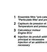
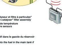
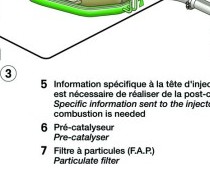
The particle
filter system consists of the following :
-
a
housing containing the pre-catalyst and filter.
The filter is a porous
block of silicon carbide that traps all particles
in the exhaust gases.
Sensors monitor clogging pressure across the
filter and the gas
temperatures at the inlet and outlet of
-
the system ;
-
a
software programme in the engine control unit that
controls
regeneration of the filter by post-injection every
400 to 500 km
depending on the clogging pressure across the
filter. The software also
provides diagnostic information on the system.
During regeneration, the
inlet air is no longer cooled by passing through
the air-air
intercooler but is instead heated to raise the
temperature of the
mixture in the combustion chamber with a
consequent increase in the
temperature of the exhaust gases ;
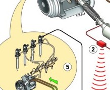
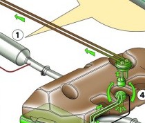
-
a
fuel additive system consisting of a probe tube, a
system to inject
Eolys into the main fuel tank and a dedicated
electronic controller.
The Eolys is stored in a tank adjacent to the main
fuel tank and
injected in proportion to the volume of fuel added
during refuelling.
For example, when filling up with 60 litres of
fuel, the system will
inject 37.5 ml of solution containing 1.9 g of
cerine. The Eolys tank
has a capacity of 5 litres, sufficient for 80,000
km.
The filter is
cleaned and the Eolys tank refilled during dealer
servicing every 80,000 km.
|
 |
©
2000 Julian Marsh/Citroënët/SA Automobiles Citroën
|
|
|